Let's Read hbird_e203 CPU Together

Copyright Notice:
This article is licensed under CC BY-NC-SA 4.0.
Licensing Info:
- Title: Let’s Read hbird_e203 CPU Together
- Author: EleCannonic
- Link: https://elecannonic.github.io/categories/electronics/read_e203/
Commercial use of this content is strictly prohibited. For more details on licensing policy, please visit the About page.
Note: This article is merely a thought process. Please do not use it as a handout, as it does not provide enough information for systematic learning. Using it as a reference is OK, though.
As a start to deep dive into the world of CPU,
hbird_e203 is a good project.
The following is the project link: Hummingbird E203
1. Instruction Set Architecture (ISA)
hbird_e203 applies RISC-V ISA,
which is designed simply.
Instrictions in RISC-V ISA are ordered strictly.
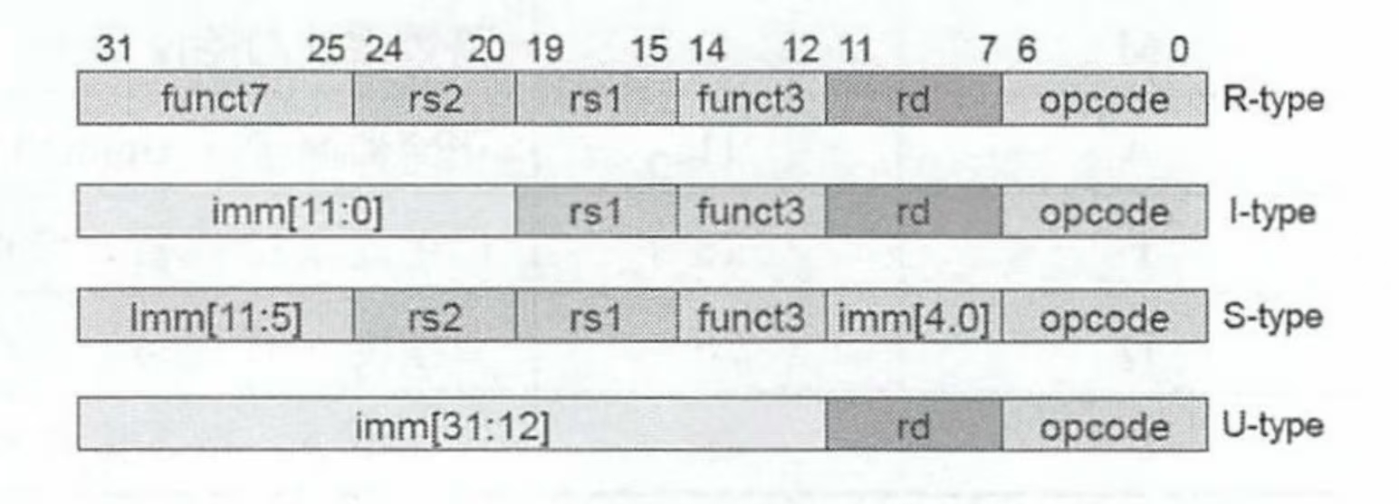
RISC-V only supports little-endian.
What is little-endian and big-endian?
Well, let’s use a figure to interpret:
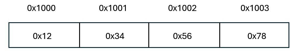
If the ISA applies little-endian,
the data stored is 0x78563412.
If big-endian,
it should be 0x12345678.
2. Standard DFF Registers
hbird_e203 uses modulized, standard DFF module to construct registers,
instead of using always block.
1 | wire flg_r; // output signal |
In another module, sirv_gnrl_dfflr is designed below:
1 | module sirv_gnrl_dfflr # ( |
Using standard modules,
it’s convenient to replace type of registers or insert delay globally.
The xchecker module captures undefined state.
Once detected, it reports an error and aborts simulation.
3. if-else and assign
This project recommends replacing if-else with assign.
Because if-else has two major drawback:
if-elsecannot transmit undefined stateX.1
2
3
4if(flg)
out = in1;
else
out = in2;If
flg == X, verilog will equate this toflg == 0,
the final output will beout = in2,
which did not transmitXstate.However, if
assignused1
assign out = flg ? in1 : in2;
The
Xstate will be transmitted.
Such transmission will make debug easier.if-elsewill be synthesised as a priority MUX,
which brings large area and worse timing.
Let’s take the MUX below for example:1
2
3
4
5
6
7
8if (sel1)
out = in1[3:0];
else if (sel2)
out = in2[3:0];
else if (sel3)
out = in3[3:0];
else
out = 4'b0;After synthesis, this code turns to

Priority MUX
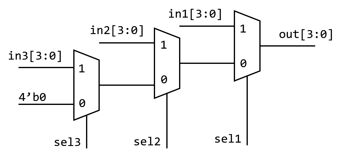
3 MUX will obviously occupy larger area.
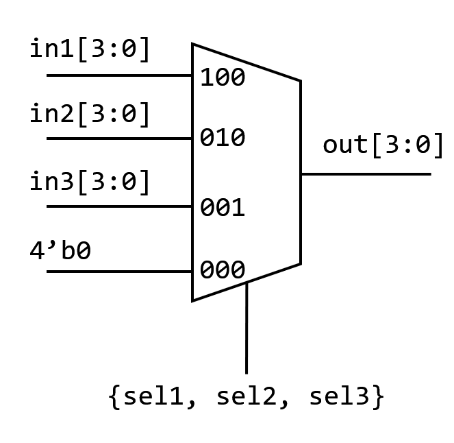
But if we use assign:
1 | assign out = ({4{sel1}} & in1[3:0]) |
This is a parallel, gating MUX.
The sel signals act as gating controls,
which are parallel for the three in signals.
It will be synthesised as
4. Data Hazard
RAW (Read After Write)
Suppose instructionjneeds an operation number,
which should be provided by instructioni.
Hence, WB ofimust be executed before the register reading ofj.For example:
1
2i: ADD x1, x2, x3 ; (x2 + x3 -> x1)
j: SUB x4, x1, x5 ; (x1 - x5 -> x4)In a pipeline,
whenjis executing ID,imight be still executing EX,
the result hasn’t been written into the register file yet.
In this situation,jwill read a wrong operation number.To solve the problem,
the pipeline can apply a stalling to pause the following instructions,
waiting for WB ofi.
But the most usual method is Data Forwarding.
CPU will send the result of EX or MEM ofitojdirectly,
instead of waiting fori.
This method increases efficiency compared to stalling.WAR (Write After Read)
Instructionjtries to write in a register,
but another instructionineeds to read the operation number in this register.
Reading ofimust be completed before writing ofj.Example:
1
2
3i: SUB x4, x1, x5 ; read x1
j: ADD x1, x2, x3 ; write x1
k: MUL x6, x1, x7 ; read x1If the pipeline is in-order,
it has no problem.
However, in an out-of-order pipeline,
ifx2andx3are ready ahead of time,jmay finish executing beforei.
Theniwill give a wrong result.To solve, CPU will rename the registers.
1
2
3i: SUB x4, P1, x5 ; // P1 for old x1 value
j: ADD P2, x2, x3 ; // P2 for new x1 value, unrelated with P1
k: MUL x6, P2, x7 ; // Use new valueTo achieve renaming,
the CPU will create a map from the external register file (ISA registers) to the internal registers.
Then the writing and reading will not influence each other anymore.WAW (Write After Write)
Two instructions,iandj,
both needs to write a number into the same register.
The correct order isifirst andjsecond.
The same, WAW also occurs in an out-of-order pipeline.
Ifjfinishes first,
the final result should be that ofi, which is wrong.The solution is also Renaming.
5. Instruction Fetch (IF)
The final target of IF is to be ‘fast’ and ‘continuously’.
ITCM
To make IF faster,
we need to make the read-delay of the memory smaller.
General memory may have a delay of dozens of clock period,
which is far from meeting our requirements.
In general, a modern CPU creates a small memory (dozens of KB)
used for store instructions,
which is physically close to the core.
This memory is called ITCM (Instriction Tightly Coupled Memory).
ITCM is not DDR or cache.
It is just a small memory with specific address.
The delay is predictable compared to cache.
Hence, in situations with high performance requirements,
engineers prefer to use ITCM.
Non-aligned Instructions
RISC-V support compressed instructions (C expansion).
CPU has to deal with a mixture of 32-bit and 16-bit instructions.
So how CPU know it is a 32-bit or a 16-bit instruction?
The least significant two bits of the opcode for a 32-bit RISC-V instruction must be 0b11.
CPU distinguishes the instructions according to the least two significant bits (call it LS2B below).
If the LS2B is 0b11, it is 32bit;
If not, it is 16bit.
So how CPU deal with them?
Let’s clarify the flow in detail.
Components
- Fetch Width: For efficiency, CPU will take more than a halfword from ITCM a time.
It usually takes more, for example 32bits. - Instruction Prefetch Queue (IPQ):
A FIFO between IFU and the decoder. - RISC-V Rule:
IfLS2B = 0b11, it is a 32bit instruction; or it is a 16bit one
- Fetch Width: For efficiency, CPU will take more than a halfword from ITCM a time.
Working Flow
According to PC value, IFU takes a word (32bit) from ITCM and inserts them into the bottom of IPQ.
ID get a halfword (16bit) from the top of IPQ, then judge whether it is a compressed instruction.
Situation A: It is a 16bit compressed instruction
ID consumes the first 16bits in IPQ and sends them to the following sections as a entire instruction.
Pointer of IPQ moves 2 bytes.Situation B: It is part of a 32bit instruction
ID needs more data. It consumes the first 32bits in IPQ and then sends them to the following section.
Pointer of IPQ moves 4 bytes.
These steps will be repeated.
When the data in the IPQ is less than 32 bits,
the IFU will perform the next 32-bit read operation and pad the data to the end of the IPQ.
Branch Instructions
There are two types of branch instructions in RISC-V.
Unconditional Jump: Judgement conditions unnecessary.
There are also two types of unconditional jump。Direct: Target address can be directly calculated by
immin the instruction.Example:
jal x5, imm,immis 20 bit, jump to address2*imm + PC.Indirect: Target address needs to be calculated from data in the register file.
Example:
jalr x1, x6, imm,immis 12 bit, jump to addressimm + x6.
Conditional Jump: Jump with conditions
Still, two types: Direct and Indirect. But there are no indirect instructions in RISC-V.
Branch Prediction
Solve two problems:
- Whether to jump (Direction)
- What’s the target address (Address)
Static prediction: Always predicting the same outcome or following a fixed pattern. (BTFN)
Jump direction: Target PC < Present PC, called back; otherwise called forward.
Dynamic:
1 bit Saturating: Using the last direction to predict.
Modify when meeting a mistake.2 bit Saturating:
Look at the state machine:
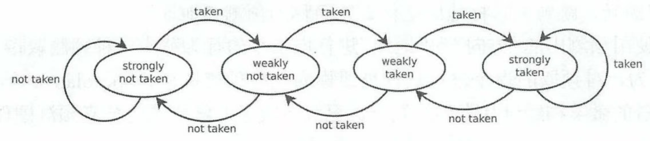
2 bit Saturating is effective in predicting one instruction.
But for many instructions (At different PC address) not.
(They will conflict)
Ideally each jump instruction should have its own predictor,
which will bring unacceptable hardware cost.
So in practice there’re only finite predictors forming a table (Branch Prediction Table).
Accurate prediction procedure: Indexing
- One instruction enters the pipeline, with
PC = 0x12345678. - CPU take lower significant sevral bits (10 for example), index
0x678 = 0d1656. - CPU accesses BPT with index
0d1656, find a 2 bit saturating predictor. - Prediction run by predictor, update states, …
In fact the instructions number is far larger than that of predictors.
Hence many different instructions have to use the same predictor.
This problem is called Aliasing.
There is a more complicated method, but with better performance,
called Correlation-Based Branch Predictor.
- Why we need it
Consider a code
1 | if (a > 10) { // branch A |
Whether B jumps dependes on both b > 20 and the result of branch A.
If A did not jump, B must not jump.
A single predictor table cannot deal with such a situation.
Two components:
- Global History Register (GHR): Width
N, record results of recentNinstructions. - Pattern History Table (PHT): An array composed by 2bit counters.
Index method: PC ^ GHR.
The 2bit counters record “when global history is in certain pattern, how branch B will act”,
instead of history of branch B itself.
Procedure:
Suppose GHR has 2bit width. Initial state 00.
Execution 1: suppose
a = 5, A not jump, recorded as0, GHR left shift, fill0to the LSB of GHR.
GHR =00.
B not jump, recorded as0, GHR left shift, fill0to the LSB of GHR.Execution 2: suppose
a = 15, b = 25, A jump, GHR =01.
Before execute B, produce index,idx = Hash(PC_B, 01).
Find a 2bit counter (suppose initial state to be11,
indicates when the last branch jumped, B tends not to jump).Make prediction: B will not jump.
Actual result: Prediction failed!
Counter:11 -> 10.
GHR:01 -> 11.
These steps repeat.
6. E200 IFU Implementation
RISC-V put the length indicator on the lowest significant bits.
Hence, the IF logic can recognize the length right after it fetches the lowest bits.
What’s more,
since the compressed instruction set is optional,
if the CPU is not designed to support compressed set,
it can directly ignore the lowest bits,
which can save about 6.25 I-cache cost.
Overall Design Concept
IFU module has such a micro-architechture:
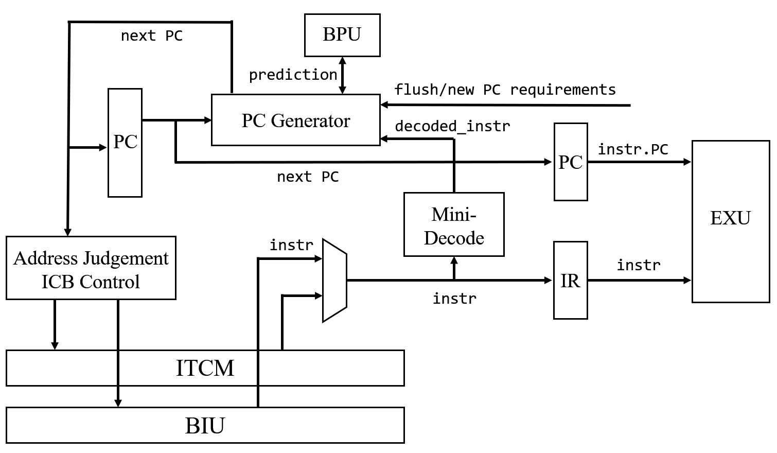
It tries to fetch instructions “fast” and “continuously”.
E203 assumes most instructions are stored in ITCM,
for it is designed for ultra-low power, embedded cases,
it will never load long codes.
Usually the codes can all be loaded in ITCM.
IF module can fetch an instruction in just one period,
which has reached the requirement of fast.
When it need to fetch instructions from BIU,
there will be more delay but such cases are much less than ITCM,
so E203 made no optimization for these cases
(for higher performance, maybe such optimization is necessary, though).
For “continuously”,
each time IF should predict the next PC value.
IF partly decodes the fetched instruction and judges whether it needs to jump.
If yes,
branch predictor runs in the same period,
and IF uses the result and decoded information to generate next PC.
Mini-decode
This module just needs to judge whether it is a general instruction or branch instruction.
To simplify design process,
this module is implemented by instantiating a complete decode module
with unrelated input grounded and output unconneted.
Synthesis tools optimize the redundant logics and finally achieve a mini-decode.
1 |
|
We will research on the decode module in detail
in the following sections, not here.
Ready/Valid Handshake
Ready/valid handshake is a protocal to ensure correct transition of data
between two equipments.
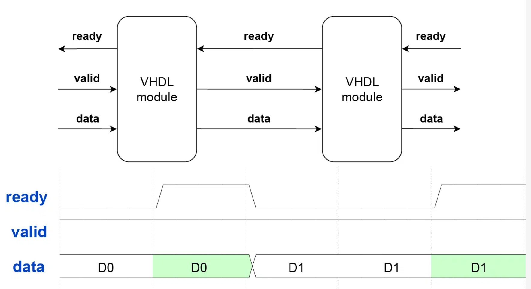
The rules are straightforward:
data transfer only happens when both ready and valid are ‘1‘ during the same clock cycle.
The handshake is a stateless protocol.
Neither party needs to remember what happened in previous clock cycles
to determine if a data transfer occurs in the current cycle.
Furthermore, both parties must operate synchronously and read the control signals on the same clock edge.
Because of that, ready/valid isn’t appropriate for clock domain crossing (CDC).
Simple BPU Branch Predictor
To achieve low power, E203 applies the most simple stationary prediction.
For conditional direct jump instructions,
a backward jump is predicted to require a jump;
otherwise, it is predicted not to require a jump.
Meanwhile BPU generates next PC by PC + offset.
The file is in module e203_ifu_litebpu.v
1 |
|
In RISC-V structure,x1 is used as a “Return Address” by default.
In most cases,jal and jalr will return the address of next instruction to x1 if not specially designated.
Hence, in most cases the address will be stored in x1.
To improve performance,
E203 implied a special acceleration to x1.
1 | wire dec_jalr_rs1x1 = (dec_jalr_rs1idx == `E203_RFIDX_WIDTH'd1); |
This line is used to judge whether jalr used x1.
Moreover, it needs to judge whether there is RAW dependency.
RAW dependency exists when
- OITF is not empty, meaning a long instruction is in execution. The result may be writen back to
x1.
(Of course it can use other registers, but conserve estimation is applied here to reduce area. The performance loss is ignored.) - Instruction in IR register will write the result back to
x1.
So
1 | wire jalr_rs1x1_dep = dec_i_valid & dec_jalr & dec_jalr_rs1x1 & ((~oitf_empty) | (jalr_rs1idx_cam_irrdidx)); |
is used to indicate dependency. The following line
1 | assign bpu_wait = jalr_rs1x1_dep | jalr_rs1xn_dep | rs1xn_rdrf_set; |
pulls up bpu_wait for one cycle if dependency is detected.
Such signal will stop next PC generation of IFU until RAW disappears.
In general, such a delay (stall) will cause a performance loss of one stall cycle.
If jalr uses other registers except x0 and x1,
E203 did not apply special acceleration.
To read xn, the 1st read port of Regfile is required.
Only when the port is empty xn can be read.
Meanwhile, IR must be empty to prevent RAW
(Similarly, ignore the performance loss).
If both RAW and read port are free,
pull up the enable of the port and occupy it
1 | wire rs1xn_rdrf_set = (~rs1xn_rdrf_r) & dec_i_valid & dec_jalr & dec_jalr_rs1xn & ((~jalr_rs1xn_dep) | jalr_rs1xn_dep_ir_clr); |
Access Memory
To improve code density,
E203 supports 16bit compressed RISC-V instruction sets.
Therefore, 32bit instructions mix with 16bit ones,
introducing misaligned 32bit instructions.
To deal with this,
E203 applies leftover buffer.
IFU fetches 32bits from the ITCM or BIU each time.
If IFU accesses ITCM,
since ITCM is composed of SRAM,
after reading, the value at the port will be hold-up (remains unchanged) until next reading.
Such property saves a 64bit register.
The bit-width of ITCM in E203 is 64bit.
One reading operation reads a 64bit data from the port, called a Lane.
When fetching by incrementing the address,
IFU fetches data from the same Lane multiple times since RISC-V instructions in E203 is at most 32bits long.
This reduces the times to read SRAM because IFU can read data from the hold-up port value until all data is read.
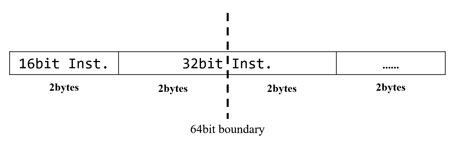
If a 32bit instruction crosses a 64bit boundary,
the leftover 16bit data will be stored in the leftover buffer
and raises a new access of SRAM.
The lowest 16bits of the new 64bit data from SRAM and the 16bits in the leftover buffer
will be concatenated into a complete 32bit instruction.
This is equivalent to fetching a 32bit instruction in one cycle,
without any performance loss.
If jump instruction or pipeline flush is encountered,
and the desired instruction crosses a 64bit boundary,
then two continuous SRAM readings are necessary.
This means the fetching must cost two cycles,
introducing one cycle loss.
E203 chooses to give up the optimization because it will bring too much extra area and consumption cost.
References:
[1] 胡振波, RISC-V架构与嵌入式开发快速入门, 第1版. 北京: 人民邮电出版社, 2019.
[2] 胡振波, 手把手教你设计CPU——RISC-V处理器, 第1版. 北京: 人民邮电出版社, 2018.